 An instrument which is used to study the small objects and its areas which can not be seen by the naked eyes or not visible with naked eyes. This instrument helps in studying the objects at micro and nano-scale lengths and studying their morphological properties. For example, microorganisms such as bacteria and yeast, mammalian cells such as cancer cells and blood cells. The Microscopy is a branch of science which involves the investigating the small objects and studying their structures using an instrument called microscope. Microscope useful in capturing images at high resolution and observe the live phenomena such as live cells and chemical reaction. There are many types of microscope and there are various ways that microscopes create or produce images. Microscopes can produce images either by sending a light beam or electrons in its optical to the samples or by scanning the surface of the samples using probes. Light microscope or optical microscope is the mostly widely used and its simplest microscope. There are other major types of microscope are available such as Electron Microscope, Scanning Electron Microscope, Fluorescence Microscope, Transmission Electron Microscope and Scanning Probe Microscope..
 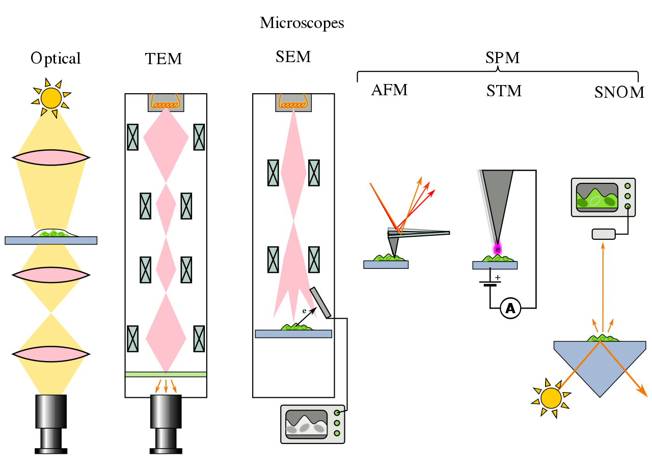 |
| Image Source: Wikipedia, Microscope Types |
A basic compound or light microsocpe has objective lens, ocular lens, eye piece, stage, reflector and lens tube. When the specimen is placed on the stage, the image is magnified by the objective lens and then through the ocular lens. A magnified image of the specimen can be observed through the eye piece.
Principle of Light Microscope:
In the light microscope, light rays which have passed through the specimen are transmitted through two sets of lenses, the objective, which is nearest to the specimen, and the eyepiece, which is further away from the specimen. The magnified image of the specimen is first produced by the objective. This is known as the primary image. The eyepiece then magnifies the primary image into the final one that is seen by the observer. The total magnification obtainable by the microscope is the product of the magnification of the objective and that of the eyepiece. (Source: learning.uonbi.ac.ke/courses)
In a simple terms:
"An illuminator (a light source) will illuminate the light and it is focused by the focusing lens which focuses this illuminated light to the specimen.. Light is then transmitted. The transmitted light then travels through the stacking of lenses to increase the magnification. Through a lens the light is focused to the eye, objective lens and a camera".
 |
| Source: http://physics.fe.uni-lj.si/students/predavanja/Microscopy_Kulkarni |
Components of a Light Microscope:
Illuminator:
Acts as a light source.. usually halogen lamp is used as light source. The light illuminated by the illuminator is focused by the condenser lens placed just below the specimen stage. The condenser lens and iris diaphragm, which filter the illuminated light and transmits the focused light on to the specimen.
Specimen Stage:
this for placing the specimen which are under study. It is also fitted with the mechanical controls which move the specimen stage in forward or backward direction or right or left.
Course Focus and Fine Focus:
These are required to focus the transmitted light on to the specimen. They are used to fine tune the light rays, so that the magnified image of the specimen can be observed properly and good quality image with good resolution can be produced.
Objective Lens:
they further magnify the images of the specimen. Commonly used objective lenses are 10x, 20x and 40x. the magnified image is then goes to the resolving nose piece.
Ocular Lens:
These are lenses through which observers can observe the magnified image of the specimen. they usually look like binoculars.
Sample images taken using light microscope:


Next: Fluorescence Microscopy, Electron Microscopy, SEM and TEM
For Reference: The Detection Limits

Comments
Post a Comment